|
|
|  FILTER TERMS
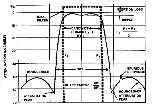
- CENTER FREQUENCY (Fo): for bandpass or band reject filters – it is the arithmetic mean of the 3 db point frequencies. Also used as the design midpoint of the passband.
- PASS BANDWIDTH (BW1): The difference between two cut-off frequencies at a specific attenuation level (-3 db or -6 db).
- INSERTION LOSS: The amount of attenuation within the passband of the filter compared to the input signal level. May be measured at center frequency or within the passband limits.
- RIPPLE: The wave like response in the passband of a filter, expressed in db. This usually means the peak to peak amplitude deviation within a specified range of frequencies in the passband.
- ATTENUATION: Reduction of signal in transmission through a filter expressed in db.
- STOPBAND ATTENUATION: A range of frequencies rejected or attenuated by the filter.
- SPURIOUS: The specified minimum level of attenuation received by all nonharmonic related resonance of each crystal resonator within the filter network.
- GROUP DELAY: The time taken for a narrow band signal to pass from the input to the output of the filter expressed in nsec or μsec.
- DIFFERENTIAL DELAY: The difference between the maximum and minimum of the group delay over a specified frequency range or two specific frequencies.
- SHAPE FACTOR: The ratio of bandwidths of two different levels of attenuation. That is: (Fo-F60)/(Fo-F3).
- INPUT/OUTPUT IMPEDANCE: Impedance presented by the filter to the outside world. The normally have both resistive and reactive components. The impedance may be expressed in VSWR, return loss, resistance and reactance or magnitude and phase angle.
- VSWR: The ratio between the voltage applied to a device and the voltage reflected or returned from that device when properly terminated.
INTERMODULATION (IM): Occurs when a filter acts as a nonlinear manner causing incident signals to mix. The new frequencies that result from this mixing are called intermodulation products. They are normally third order products. Out of band IM occurs when two input signals in the stopband produce an IM product in the filter passband. This IM is most prevalent in receivers. In band IM occurs when two closely spaced signals within the filter bandpass cause IM products. This IM is most prevalent in transmitters.
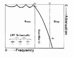
Lowpass Filters
A lowpass filter provides good transmission at frequencies below the cut-off frequency (Fc) and suppresses transmission at higher frequencies. An abrupt change from the pass to stop condition is not feasible in real filters. Therefore, a reasonable guardband is provided by specifying a stopband frequency Fr where a specific level of rejection Ar is to be achieved and maintained.
More lowpass filters are used than any other type for suppression of harmonic pf spurious outputs from transmitters or other RF signals. Lowpass filters are also used for protection of sensitive receiving equipment from strong signals at higher frequencies.
Lowpass filters can be supplied as lumped, semi-lumped constant construction or distributed elements construction depending on frequency.
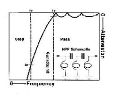
Highpass Filters
A highpass filter is a frequency inversion of a lowpass filter. A highpass filter provides good transmission at frequencies above the cut-off frequency (Fc) and suppresses transmission at lower frequencies. An abrupt change from the pass to stop condition is not feasible for real filters. Therefore, a reasonable guardband is provided by specifying a stopband frequency Fr which a specific level of attenuation Ar is to be mainained.
The highpass filter is often the most difficult to realize in practice, particularly to maintain a flat response to an indefinitely high frequency. Therefore, highpass filter are used in practice than any other type of filter. The highpass filter retains the same transmission and selectivity characteristics of the low pass filter. Good passband quality may be defined as low reflection, low insertion loss and flat time delay. In general, increasing selectivity results in decreasing passband quality.
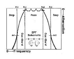
Bandpass Filters
A bandpass filter provides good transmission within its passband frequencies (Fc1 to Fc2) and lower frequencies. An abrupt change from the passband to the stopband is not feasible in real filters. Therefore, reasonable guard bands are provided by specifying lower and upper stopband frequencies (Fr 1 and Fr 2) where specified levels of rejection (Ar 1 and Ar 2) are to be achieved and maintained.
Bandpass filters are used to suppress harmonics and sub-harmonics and other spurious outputs from impacting associated equipment. Strong signals below and above the passband frequencies are suppressed to provide a clear processing frequency band.
Good passband quality may be defined as low reflection, low insertion loss and flat time delay. In general, increasing selectivity results in decreasing passband quality. Circuit complexity is proportional to selectivity as the ratio (Fr-Fr1)/(Fc2-Fc1) decreased toward 1.0 which more circuit branches are required.
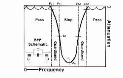
Bandstop Filters
A banstop fiter is a frequency inversion of a bandpass filter. The stopband and passband are interchanged. It suppresses the transmission of frequencies within its stopband (Fr 1 to Fr 2) and permits transmission of frequencies in the lower and upper passbands. An abrupt change from the pass to stop condition is not feasible for real filters. Therefore, a reasonable guardbands are provided by specifying a notch band (Fr 1 to Fr 2) which a specific level of attenuation Ar is to be maintained. If only a single frequency Fo is to be suppressed, one simply specifies the attenuation Ao required at Fo.
Bandstop or band reject type filters are usually superior to bandpass filters for suppressing a single carrier or a narrow spectrum adjacent to a desired passband. They protect receivers from strong adjacent interference or remove unwanted carriers to facilitate measurements of system noise.
Good passband quality may be defined as low reflection, low insertion loss and that time delay. In general, increasing selectivity results in decreasing passband quality. Circuit complexity is proportional to selectivity as the ratio (Fc2-Fc1)/(Fr2-Fr1) decreased toward 1.0 which means more circuit branches are required.
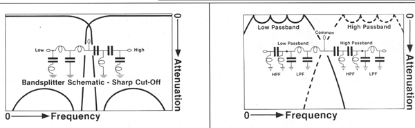
DIPLEXERS
Diplexers are filter assemblies which combine two different frequencies to a common output or split the RF spectrum into two different frequencies. They usually consist of two filters selected from the four basic type plus a coupling network.
Diplexers are often used to connect a receiver and a transmitter to a common antenna in order to minimize mutual interference. Many other applications are some variation of this. For example, two transmitters or two receivers are combined to a cable for remote signal transport where another diplexer splits the original.
OPT HELLAS offers two types of Diplexers.
The Lowpass/Highpass type which is commonly used in wide band splitting applications.
Bandpass/Bandpass Diplexers are used in situations where two narrow band signals have to be combined or split into a single channel.
Duplexers
In every duplex system, the receiver must be adequately isolated from its transmitter, if normal receiver performance is to be expected. Isolation (db) is required to protect the receiver from transmitter spurious and noise radiation and receiver desensitization. The amount of isolation required to protect a receiver from the associated transmitter is related to separation between transmit receive frequencies. As the frequency separation is decreased, the isolation must be increased if normal receiver performance is to be expected.
Once the amount of isolation required for a duplex station is determined, the isolation can be achieved by either using two antennas separated by a given distance, or by using appropriate duplexer.
There are many advantages to using a duplexer.
- With the use of a duplexer, the transmitter can be connected to a single antenna, thus eliminating the need of a second antenna and transmission line.
- The use of a single antenna assures the same radiation for both transmitter and receiver which might otherwise be impossible to achieve.
- The use of single antenna simplifies the search for a suitable location for mounting the antenna.
There are basically three types of duplexers use in the two way radio communication industry. The bandpass duplexer, the bandreject duplexer and the combination of the two (bandpass/bandreject). Each type has its advantages and disadvantages. No matter what type is selected, the duplexer must meet certain requirements if optimum system performance is to be achieved. A duplexer must:
- Obviously be designed for operation in the specific frequency band in which the duplex system operates.
- Be capable of handling the output power of the transmitter.
- Be designed for operation at the frequency separation between the transmit and receive frequencies.
- Provide adequate rejection to transmitter noise occurring at the receive frequency. It is better to have more rejection than not enough.
- provide sufficient isolation to prevent receiver desensitization. Again, too much isolation is satisfactory but inadequate isolation will result in degradation of receiver performance.
- Offer as little insertion loss as possible to the desired transmit and receive frequencies.
The output signal from the transmitter and the incoming signal to the receiver are both reduced by losses in the duplexer. These losses are referred as Insertion Loss in the duplexer specifications and expressed in db. Generally the Insertion Loss will increase as the separation between transmit and receive frequencies is decreased.
- For the transmitter, insertion loss values of 0.5 db, 1.0 db and 2.0 db corresponds to a reduction of output in Watts of approximately 11%, 20% and 37% respectively.
- For the receiver, insertion loss values of 0.5 db, 1.0 db and 2.0 db corresponds to a signal strength (microvolts) reduction of 5%, 11% and 20% respectively.
Bandpass / Bandpass Duplexers
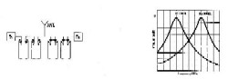
The use of bandpass duplexers is considered by many to be the best choice of all duplexers because of the overall protection it provides. The bandpass duplexers not only prevent the receiver from being desensitized by its associated transmitter but provide some protection from the other transmitters in the area as well. Transmitter spurious and noise radiation that would otherwise occur at the frequency of the associated receiver is attenuated by the duplexer. In addition, the duplexer attenuates noise energy being radiated by the transmitter on other frequencies as well and this characteristic provides some degree of protection to the other receivers in the area. It is very effective in reducing or eliminating intermodulation interference in the front end of the receiver. For these reasons, the bandpass duplexers is ideally suited for use in most duplex systems, particularly those located in frequency congested areas. In comparison with other types of duplexers, the bandpass duplexers have slightly higher insertion loss at the desired transmit and receive frequencies. Bandpass duplexers are used in duplex systems with wider frequency separation. This is the only disadvantage of this type of duplexer.
Bandreject / Bandreject Duplexer
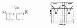
This type of duplexer consists of tow bandreject filters interconnected in duplex configuration. It is used more often than any other type of duplexer because of its compact size, low insertion loss at the desired transmit and receive frequencies and excellent isolation features. This type of duplexer is suitable with wide and close spacing between transmit and receive frequencies. Unlike the bandpass type, the bandreject duplexer does not change the overall transmitter noise output. Instead, it selectively attenuates transmitter noise at the critical band of frequencies at and near the receiver characteristics. It changes only a portion of the selectively response and makes the receiver unresponsive to the critical band of frequencies at and near the transmit frequency. A bandreject duplexer is designed primarily to protect the receiver from its associated transmitter. If the duplex system is located in frequency congested area, additional protection to and from other stations is required. Additional protection can be accomplished by using one or more bandpass cavities between the transmitter and the duplexer and between the receiver and the duplexer.
|
|
|